Services
Strength Test
Chemical Test
- pH Value
- Chloride Content
- Sulphate Content
- Organic Content
- Carbonate Content
- Soil Resistivity
Classification Test
Moisture Content
Introduction
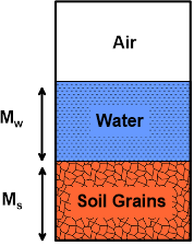
The water content (w), also known as natural water content or natural moisture content, is the ratio of the weight of water to the weight of the solids in a given mass of soil. This ratio is usually expressed as percentage. When voids are completely filled with air, water content is equal to zero (dry soil).
w(%) = (MW / MS) * 100
Objectives
To determine the amount of moisture (water) content present in the given of quantity of soils in terms of its dry weight by direct heating.
Apparatus Required
- Non-corrodible container;
- Digital Weight Machine (accuracy of 0.04% of mass of sample);
- Electric oven, maintain the temperature between 1050 C to 1100 C
Test Procedure (Oven Dry Method)
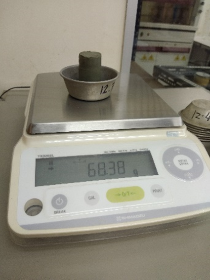
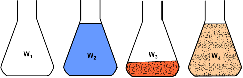
- Clean and dry the container and weigh it (W1).
- Take a specimen of the sample in the container and weigh it (W2).
- Place the container in the hot air oven, arrange temperature to 110o ± 5o C and allow it to dry for a period varying with the type of soil (usually 24 hours).
- Record the final constant weight (W3) of the container with dried soil sample.
| Sample No. | 1 | 2 |
|---|---|---|
| Weight of container W1 (g) | ||
| Weight of container + wet soil W2 (g) | ||
| Weight of container + dry soil W3 (g) | ||
| Moisture content w(%)=((W2– W3)/( W3– W1))*100 |
Unit Weight
Introduction
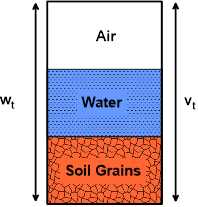
Unit weight of a soil mass is the ratio of the total weight of soil to the total volume of soil.
Unit Weight, ɣ, is usually determined in the laboratory by measuring the weight and volume of a relatively undisturbed soil sample obtained from drilling thin-walled cyclinder.
γ = wt/vt
Objectives
To determine the in-place density of soils.
Apparatus Required
- Non-corrodible container;
- Vernier caliper
- Digital Weight Machine (accuracy of 0.04% of mass of sample);
Test Procedure
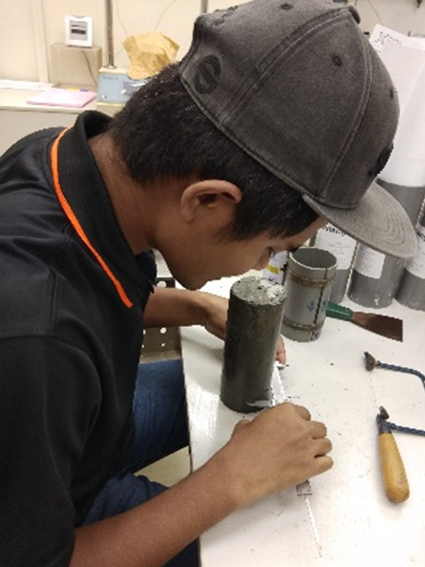
- Extrude the soil sample from the cylinder using the excluder.
- Cut a representative soil specimen from the extruded sample.
- Determine and record the length (L), diameter (D) and Mass (Mt) of the soil specimen.
- Determine and record the moisture content of the soil (Wt).
- Note: If the soil is sandy or loose, weight the cylinder and soil sample together. Measure dimensions of the soil sample within the cylinder. Extrude and weight the soil sample and determine moisture content.
Specific Gravity
Introduction
Soil is a three-phase material that consists of solid particles and voids which are filled with water and air. The specific gravity (GS) of a soil refers to the ratio of the solid particles’ unit weight to the unit weight of water. GS should not be confused with the soil density since it is a dimensionless unit and expresses the ratio of two particular densities.
GS is a significant parameter of soil mechanics since it can be associated with the soil’s mineral composition and weathering. It is also used to derive several important soil parameters such as the porosity, the dry and saturated density and the degree of saturation.
Objectives
To determine the specific gravity of soil fraction passing 4.75mm by density bottle.
Apparatus Required
- Volumetric flask marked with a thin ring at a specific point of its neck (graduation mark)
- Balance sensitive to 0.01g
- Vacuum pump
- Distilled water
- Funnel
- Spatula
- Drying oven
Test Procedure
The Specific Gravity is computed as the ratio of the weight in air of a given volume of soil particles at a stated temperature to the weight in air of an equal volume of distilled water at the same temperature. The procedure that is followed towards that goal is the following:
- Weigh the empty and clean volumetric flask (W1).
- Fill the flask with distilled water up to the graduation mark.
- Clean and dry the inside (above the water level) and the outer part of the flask and weigh it (W2).
- Empty and dry the Flask
- Weigh around 50 grams of soil material.
- Use the funnel to carefully place the soil into the flask and weigh it (W3).
- Fill around 2/3 of the flask with distilled water.
- Use a vacuum pump to gradually apply vacuum and remove the entrapped air while spinning the flask to remove the air bubbles. The procedure should last for about 2-3 minutes for sands and 10-15 minutes for clays.
- Remove the vacuum, clean and dry the flask and add distilled water up to the mark.
- Weigh the flask (W4).
- Use the thermometer to derive the temperature of the water.Volumetric flask marked with a thin ring at a specific point of its neck (graduation mark)
The Specific Gravity of soils generally ranges between 2.63-2.90 with finer soils having higher values than coarser ones. Organic matter and porous particles may have specific gravity value below 2.0 and soil which has heavy substance or particles may have values above 3.0.
| Soil Type | Range of GS |
| Sand | 2.63 – 2.67 |
| Silt | 2.65 – 2.70 |
| Clay and Silty Clay | 2.67 – 2.90 |
| Organic Soil | Less than 2 |
Grain Size Analysis
Introduction
Grain size analysis is a typical laboratory test conducted in the soil mechanics field. The purpose of the analysis is to derive the particle size distribution of soils.
The analysis is conducted via two techniques. Sieve Grain Size Analysis is capable of determining the particles’ size ranging from 0.075 mm to 100 mm. Any categorization of grains larger than 100 mm will be conducted visually whereas particles smaller than 0.075 mm can be distributed using the Hydrometer Method.
Sieve Grain Size Analysis
The test is carried out with the utilization of a set of sieves with different mesh sizes. Each sieve has squared shaped openings of a certain size. The sieve separates larger from smaller particles, distributing the soil sample in 2 quantities. The grains with diameters larger than the size of the openings are retained by the sieve, while smaller diameter grains pass through the sieve. The test is conducted by placing a series of sieves with progressively smaller mesh sizes on top of each other and passing the soil sample through the stacked sieve “tower”. Therefore, the soil particles are distributed as they are retained by the different sieves. A pan is also used to collect those particles that pass through the last sieve (No. 200).
The nomenclature of the sieves typically used for Grain Size Analysis of soils as well as the corresponding opening sizes are presented in Table 1. Based on the range of the particle sizes, and the Unified Soil Classification System (USCS), soils can be classified in the generic categories presented in Table 2. Further categorizations are possible upon further analysis of the Grain Size Distribution results.
| Sieve # | Opening Diameter (mm) |
| 4 | 4.75 |
| 10 | 2.00 |
| 20 | 0.85 |
| 40 | 0.425 |
| 60 | 0.25 |
| 100 | 0.15 |
| 140 | 0.105 |
| 200 | 0.075 |
| Soil Type | Particle Size (mm) | |
| Clay | <0.002 | |
| Silt | 0.002-0.075 | |
| Sand | Fine | 0.075-0.42 |
| Medium | 0.42-2.0 | |
| Coarse | 2.0-4.75 | |
| Gravel | 4.75-75 | |
Apparatus Required
- Drying oven maintained at 110 ± 5°C
- Standard sieves
- Sample splitter
- Mechanical sieve shaker
- Pans
Sieve Test Procedure
- Weigh a dry soil sample which should be at least 500 gr.
- Record the weight of the sieves and the pan that will be utilized during the analysis. Each sieve should be thoroughly cleaned up before the test.
- Assemble the sieves in ascending order, placing those with the larger openings on top. Therefore, the No. 4 sieve should be on top and the No. 200 sieve on the bottom of the stack.
- Place the soil sample into the top sieve and place a cap/lid over it.
- Place the stack in a mechanical shaker and shake for 10 minutes
- Remove the sieve stack from the shaker and measure the weight of each sieve and that of the pan placed at the bottom of the stack.
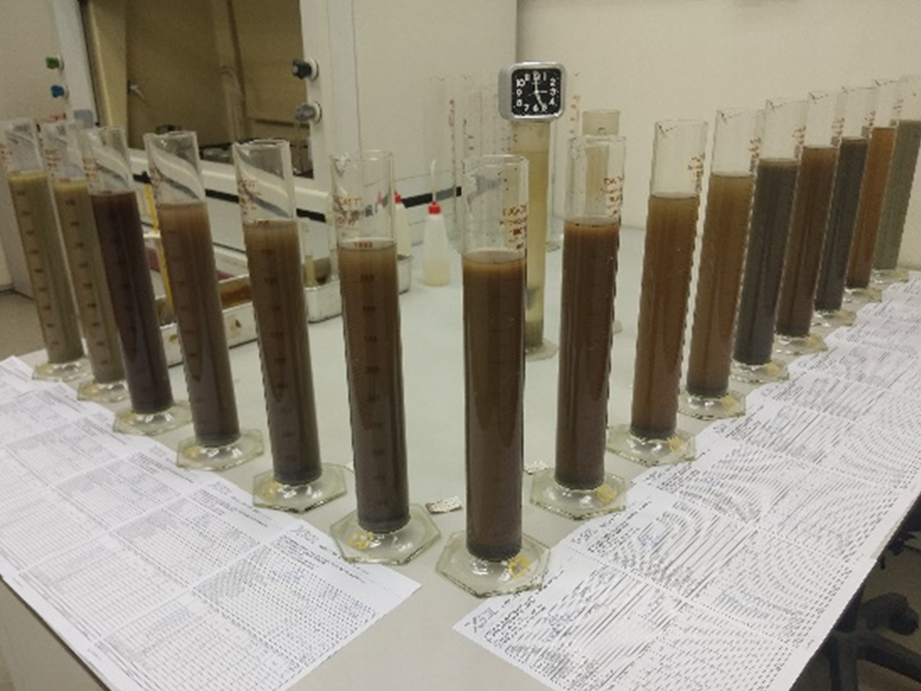
Hydrometer Grain Size Analysis
The hydrometer analysis is utilized for particle sizes finer than 75 μm. These particles pass through the last sieve (No. 200) of the Sieve Analysis.
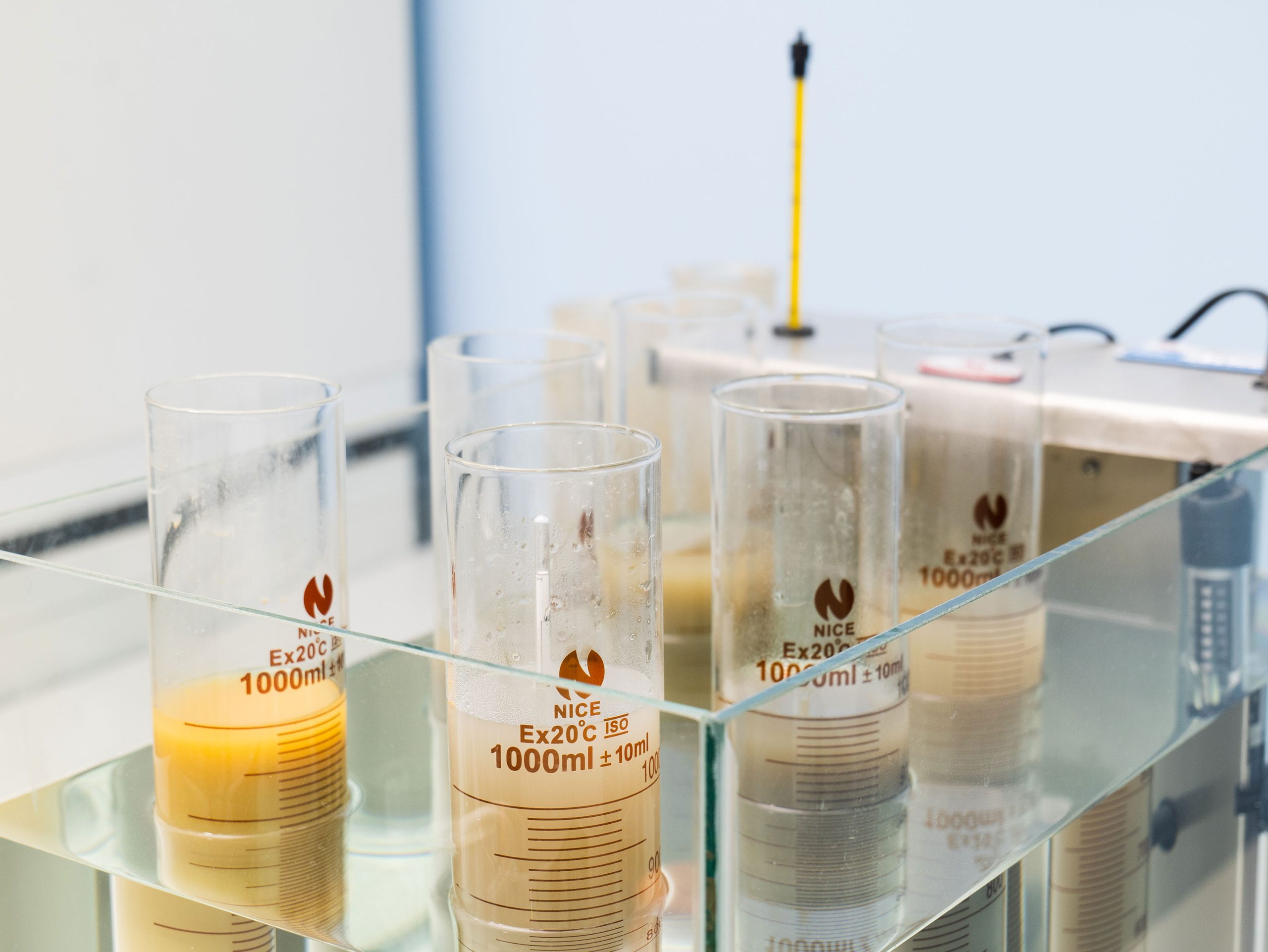
A hydrometer is a device designed to measure the relative density of a liquid which refers to the ratio of the actual density of the substance to the density of the water. The apparatus consists of a cylindrical stem and a bulb that contains a specific portion of mercury or lead at the bottom, calibrated to float upright in the liquid. The liquid is poured in a tall cylinder usually made out of glass and the hydrometer is placed inside until it is stabilized. The test is based on the principle that in a low-density liquid, the hydrometer will sink deeper until it balances.
The hydrometer contains a scale which is used to record the relative density of the liquid based on its submersion.
The hydrometer grain size analysis takes advantage of the change in the relative density of a soil-water mixture as the soil particles sink. The test relies on the fact that when the soil is poured in the liquid, the relative density of the soil-water mixture will rise. As the soil particles sink the density decreases until it reaches the initial density of the liquid. The heaviest particles (larger in diameter) will sink first.
Apparatus Required
- Hydrometer device
- Drying oven maintained at 110 ± 5°C
- Stirring apparatus
- 2 glass containers, each of 1000 ml volume
- Mercury thermometer ranging from 0–104 °C
- Dispersing agent
- Desiccator
- Stopwatch
- Distilled water
Hydrometer Test Procedure
- Sieve enough soil by hand through the #40 sieve
- Dry soil at 110 ± 5° C overnight
- Utilize a desiccator to place the sample and allow it to cool.
- Record the dry weigh of the soil (typically, 50 gr)
- Place 500-600 ml of distilled water in a steel mixing cup.
- Add 5 gr of sodium hexametaphosphate solution and utilize a high-speed mixer to disperse it (~3 min.).
- Add the soil to the mixture and mix for 5-6 minutes.
- Clean the blade as no material should be lost.
- Place the mixture in a 1-liter cylindrical container and fill it with distilled water.
- Place a rubber cap on top of the cylinder and turn the container upside down multiple times.
- Right after shaking, place the container on top of a table and start measuring time.
- Slowly insert the hydrometer device into the container and take readings at 10, 20, 40, 60 and 120 seconds, respectively. The measurement should be taken at the top of the formed meniscus. Utilize a thermometer to measure the temperature.
- Right after the 2 minutes reading, remove the hydrometer and place it into another container with distilled water.
- Carefully insert the hydrometer and take subsequent measurements at 4, 6, 8, 15, 30, 60 and 90 minutes. Between readings, place the rubber cap on top of the container.
Atterberg Limits
Introduction
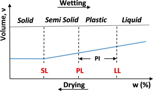
The consistency and behaviour of a clayey soil is different as are the engineering properties at varying degrees of moisture content. Thus, the boundary between each state can be defined based on a change in the clay’s behaviour. Swedish scientist Albert Atterberg was the first person to define the limits of soil consistency for the classification of fine-grained soils and later, they were refined by Arthur Casagrande. Depending on the water content of a soil, the soil may be in one of four states: solid, semi-solid, plastic and liquid. These methods are still being used to determine the Liquid Limit, Plastic Limit and Shrinkage Limit of soils, which are outlined in ASTM D4318 (Figure 1).
Objectives
To determine the plastic and liquid limits of a fine-grained soil.
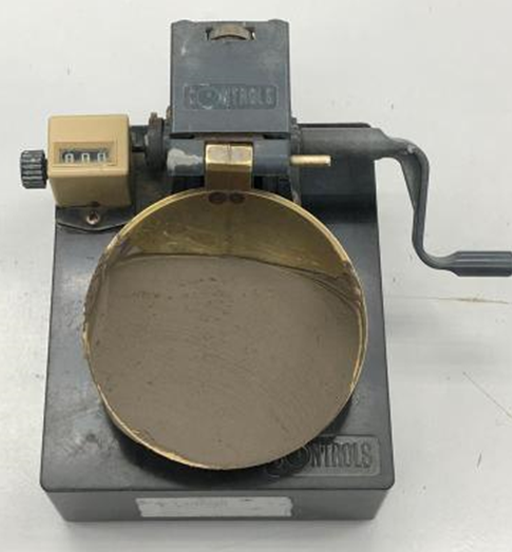
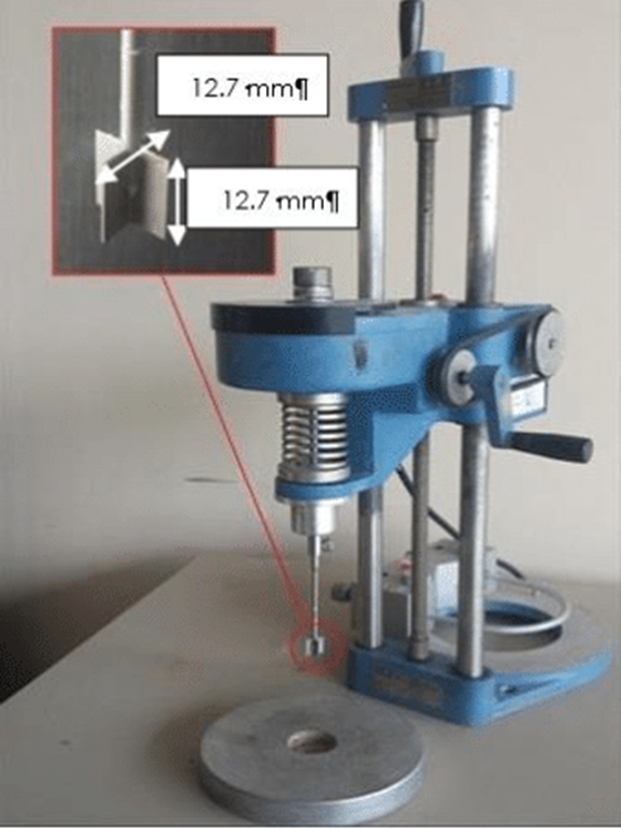
Liquid Limit
The Liquid Limit (LL or wLL), also known as the upper plastic limit, is the water content at which the soil changes from the liquid state to a plastic state. It is the minimum moisture content at which a soil flows upon application of very small shear force.
The precise definition of the liquid limit is based on standard test procedures. Liquid Limit can be determined using the Casagrande cup method or a cone penetrometer.
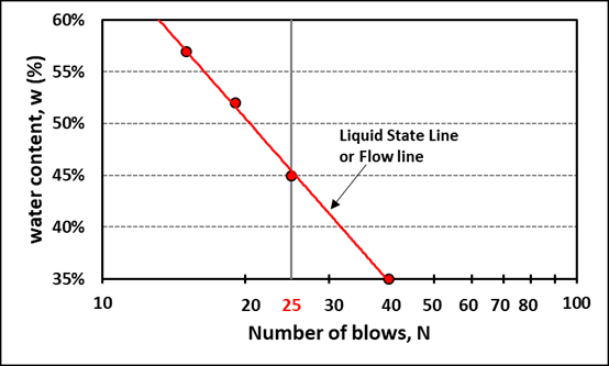
In the Casagrande cup method, the soil paste is placed in the Casagrande cup, and a groove is made at the centre of it (see procedure below). The limit is defined as the moisture content, in percent, required to close a distance of 0.5 inches along the bottom of a groove after 25 blows in a liquid limit device. It is difficult to adjust the moisture content in the soil to meet the required 12.5 mm (0.5 in.) closure of the groove in the soil pat at 25 blows. Hence, at least three tests for the same soil are conducted at varying moisture contents, with the number of blows, N, varying between 15 and 35.
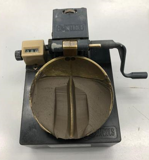
Liquid Limit Test Procedure
- Place a soil paste in the cup.
- Cut a groove at the centre of the soil paste with the standard grooving tool.
- Lift the cup and drop it from a height of 10mm, using the crank-operated cam. Measure the water content required to close a distance of 12.7mm along the bottom of the groove and note down the number of blows.
- Repeat the procedure at least three times for the same soil at varying moisture contents.
- Plot the moisture content of the soil, in percent, and the corresponding number of blows on semi-logarithmic graph. Draw the best-fit straight line through the plotted points.
- The moisture content corresponding to N 25, determined from the curve, is the liquid limit of the soil.
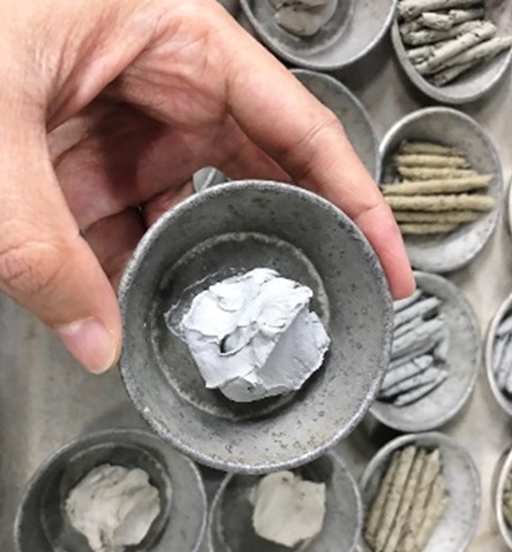
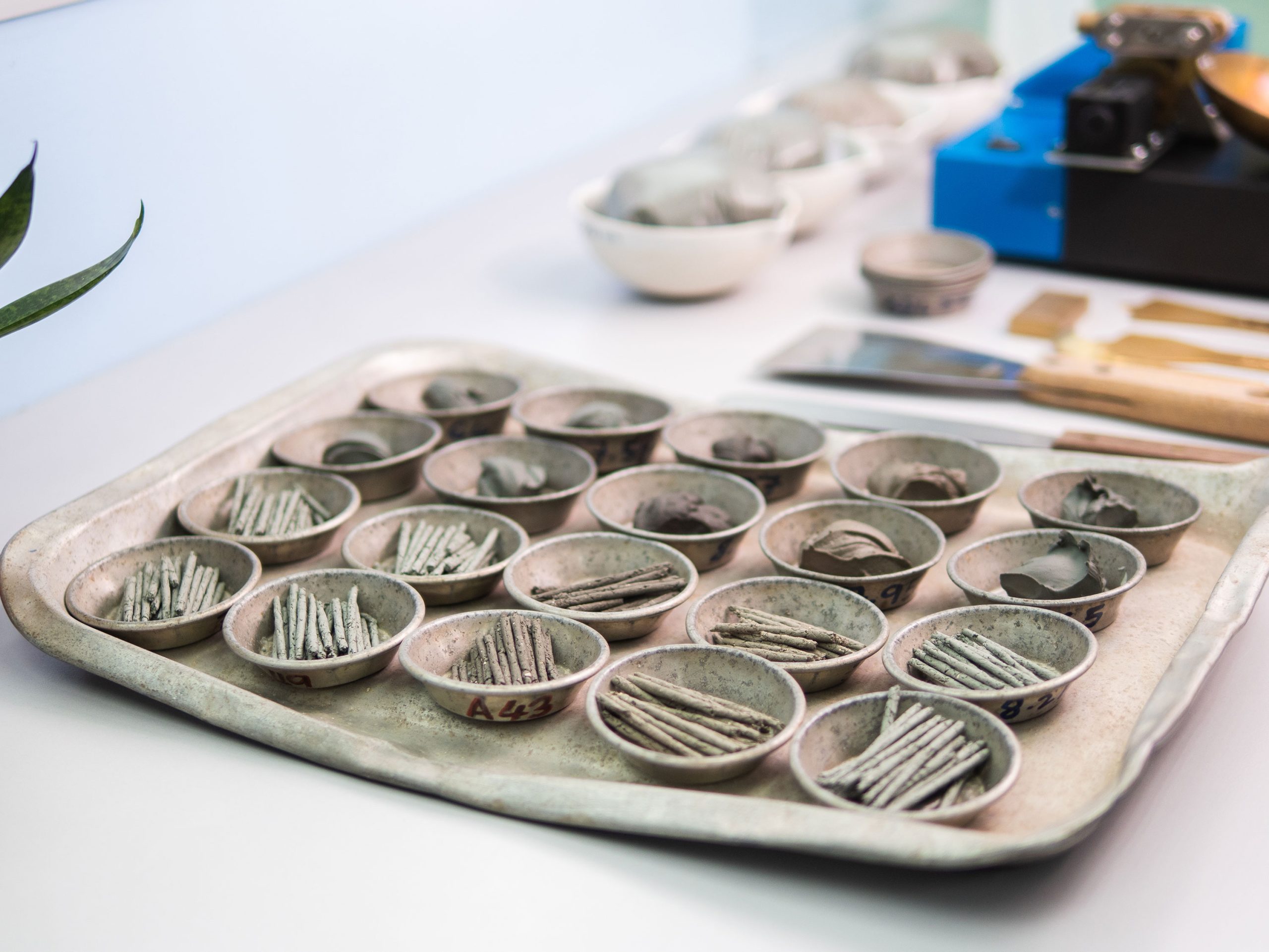
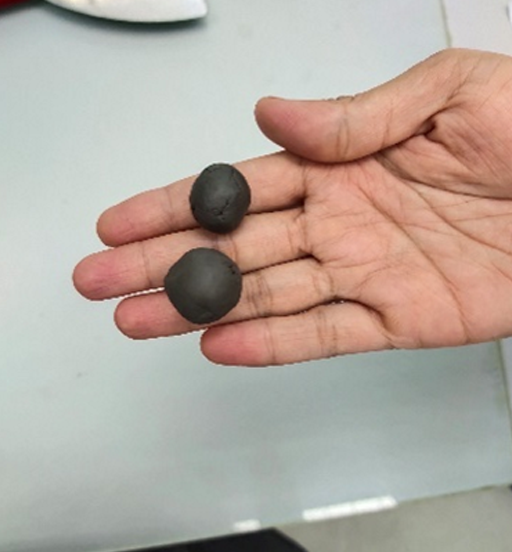
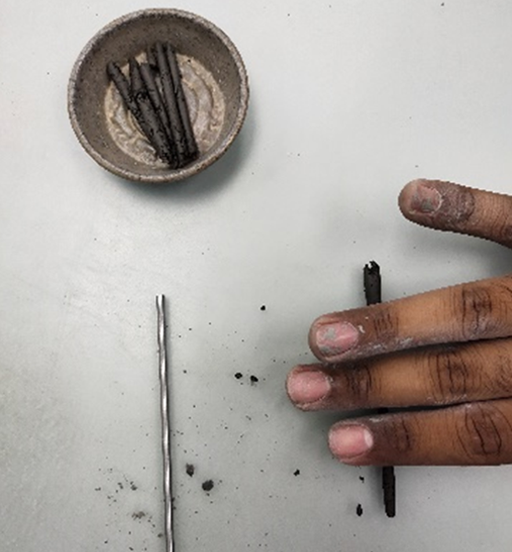
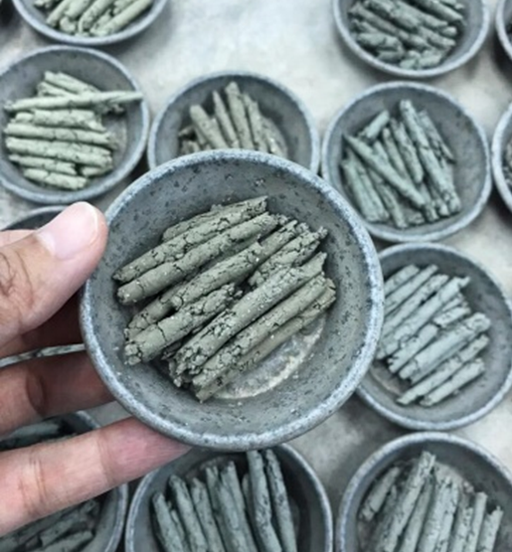
Plastic Limit
The Plastic Limit (PL or wPL), also known as the lower plastic limit, is the water content at which a soil changes from the plastic state to a semisolid state. The Plastic limit test is performed by repeated rolling of an ellipsoidal-sized soil mass by hand on a non-porous surface. Casagrande defined the plastic limit as the water content at which a thread of soil just crumbles when it is carefully rolled out to a diameter of 3 mm (1/8”). If the thread crumbles at diameter smaller than 3 mm, the soil is too wet. If the thread crumbles at a diameter greater than 3 mm, the soil is drier than the plastic limit. The sample can then be remoulded and the test repeated. Once the appropriate size rolls are made, their moisture content is assessed using the procedure described previously.
Plasticity Index
Plasticity Index (PI or IP) is calculated as the Plastic Limit subtracted from the Liquid Limit and is an important value when classifying soil types.
PI = LL – PL
Linear Shrinkage
Introduction
Linear shrinkage is the decrease in length of a soil sample when oven-dried, starting with a moisture content of the sample at the liquid limit.
Objectives
To determine the linear shrinkage of the fraction of a soil sample passing a 425 µm test sieve.
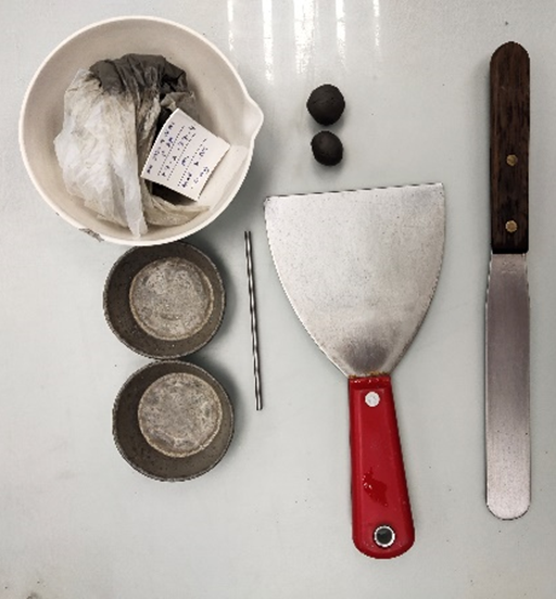
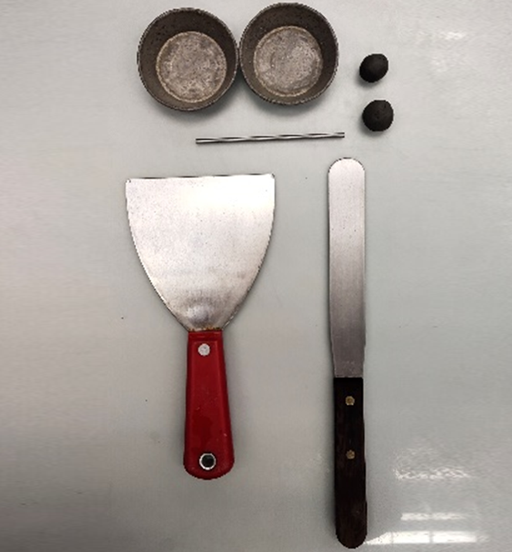
Apparatus Required
- Shrinkage Mould;
- Electric oven, maintain the temperature between 1050 C to 1100 C
Test Procedure
- A sample weighing 150g from thoroughly mixed portion of bulk material passing 425µm sieve is prepared.
- The mould is thoroughly with distilled water, using palette knives, until the mass becomes a thick homogeneous paste.
- The thoroughly mixed soil-water paste is placed in the mould such that it is slightly above the sides of the mould.
- Then the mould with the soil paste is dried in the oven maintained at a temperature of 1050 C to 1100 C.
- After complete drying, the mould and soil is cooled and the mean length of the soil bar is measured.
Calculation
Linear Shrinkage = [1-(Length of oven dried specimen / Initial length of specimen)] x 100
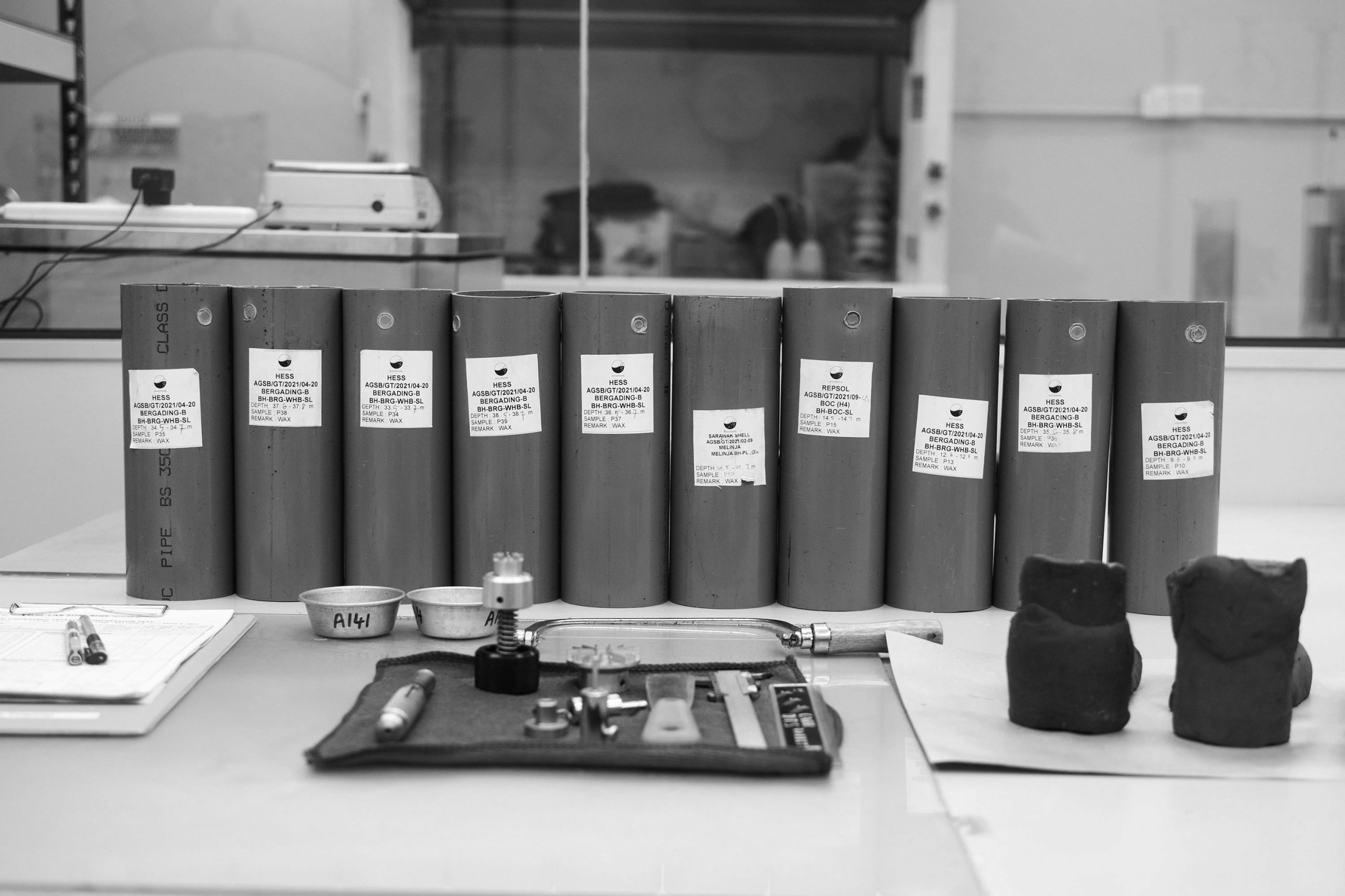
Soil Description
Soil description/identification is the systematic naming of individual soils in both written and spoken forms (ASTM D 2488, AASHTO M 145). Soil classification is the grouping of soils with similar engineering properties into a category by using the results of laboratory-based index tests, e.g., group name and symbol (ASTM D 2487, AASHTO M 145). It is important to distinguish between a visual description of a soil and its classification in order to minimize potential conflicts between general visual evaluations of soil samples in the field and more precise laboratory evaluations supported by index tests.
The soil’s description should include as a minimum:
- Apparent consistency or density adjective
- Water content condition adjective (e.g., dry, moist, wet)
- Colour description (e.g., brown, grey, etc)
- Main soil type name, often presented in all capital letters (e.g. SAND, CLAY, SILT)
- Description adjective for main soil type (e.g., fine, medium, coarse, well-rounded, angular, etc. for coarse-grained soils; organic, inorganic, compressible, laminated, etc., for fine-grained soils)
- Particle-size distribution adjective for gravel and sand (e.g., uniform, well-graded, etc)
- Plasticity adjective (e.g., high, low) and soil texture (e.g., rough, smooth, slick, waxy, etc.) for inorganic and organic silts or clays
- Descriptive term for minor type(s) of soil (with, some, trace, etc.);
- Descriptive adjective “with” if the fine-grained minor soil type is 5 to 12 percent (e.g., with clay) or if the coarse-grained minor soil type is less than 30 percent but 15 percent or more (e.g., with gravel). Note: some practices use the descriptive adjectives “some” and “trace” for minor components
- Inclusions (e.g., concretions, cementation)
For example, a soil description might be presented as follows:
Fine-grained soils: Soft, wet, grey, high plasticity CLAY, with fine sand
Soil Classification
Final identification with classification is best performed in the laboratory. This process will lead to more consistent final boring logs and avoid conflicts with field descriptions. The Unified Soil Classification System (USCS) group name and symbol (in parenthesis) appropriate for the soil type in accordance with AASHTO M 145 (or ASTM D 3282) or ASTM D 2487 is the most commonly used system in geotechnical work and is covered in this section. For classification of highway subgrade material, the AASHTO classification system (see Section 4.2.2) is used. The AASHTO classification system is also based on grain size and plasticity.
| Criteria for Assigning Group Symbol and Group Names Using Laboratory Tests COARSE-GRAINED SOILS (Sands and Gravel) – more than 50% retained on No.200 (0.075mm) sieve FINE-GRAINED SOILS (Silts and Clays) – 50% or more passes the No.200 (0.075mm) sieve | Soil Classification | |||||
| Group Symbol | Group Name | |||||
| GRAVELS More than 50% of coarse fraction retained on No.4 sieve | Clean Gravels <5% fines | Cu≥4 and 1≤Cc≤3 | GW | Well-graded Gravel | ||
| Cu<4 and/or 1>Cc>3 | GP | Poorly-graded Gravel | ||||
| Gravels with Fines >12% fines | Fines classify as ML or MH | GM | Silty Gravel | |||
| Fines classify as CL or CH | GC | Clayey Gravel | ||||
| SANDS 50% or more of coarse fraction passes No.4 sieve | Clean Sands <5% fines | Cu≥6 and 1≤Cc≤3 | SW | Well-graded Sand | ||
| Cu<6 and/or 1>Cc>3 | SP | Poorly-graded Sand | ||||
| Sands with Fines >12% fines | Fines classify as ML or MH | SM | Silty Sand | |||
| Fines classify as CL or CH | SC | Clayey Sand | ||||
| SILTS AND CLAYS Liquid limit less than 50% | Inorganic | PI>7 and plots on or above “A” line | CL | Lean Clay | ||
| PI<4 or plots below “A” line | ML | Silt | ||||
| Organic | Liquid limit-overdried Liquid limit-not dried | <0.75 | OL | Organic Clay Organic Silt | ||
| SILTS AND CLAYS Liquid limit 50% or more | Inorganic | PI plots on or above “A” line | CH | Fat Clay | ||
| PI plots below “A” line | MH | Elastic Silt | ||||
| Organic | Liquid limit-overdried Liquid limit-not dried | <0.75 | OL | Organic Clay Organic Silt | ||
| Highly Fibrous Organic Soils | Primary organic matter, dark in colour and organic odor | Pt | Peat | |||
The Unified Soil Classification System (ASTM D 2487) groups soils with similar engineering properties into categories base on grain size, gradation and plasticity. Table 1 provides an outline of the complete laboratory classification method. The procedures, along with charts and tables, for classifying coarse-grained and fine-grained soils follow.
Strength Test
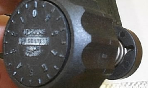
Torvane
The Torvane is a hand-held instrument with attachments calibrated to shear strength for clays varying in consistency from very soft to stiff. Three sizes of vanes are supplied with each Torvane.
Objectives
To determine the shear strength in cohesive soils.
Test Procedure
- Select desired vane size and fit to vane driver
- Make sure zero on dial is aligned with index mark on knob. A counter-clockwise rotation of the dial face (while holding onto the vane) brings the zero mark on the dial face back to the index mark.
- Test surface should be reasonably flat and at least two inches in diameter. Press Torvane into soil to depth of blades and maintain a constant pressure while turning the knob. A rate of rotation such that failure develops in five to ten seconds is recommended.
- After failure develops, release the remaining spring tension slowly and the index mark on the knob will indicate the maximum shear value.
There are three (3) vane sizes:
| Vane Name | Base Number | Strength Range (kg/cm2) | Strength Range (kPa) | Conversion Factor to kPa |
| Sensitive | 0.2 | 0.0 – 0.2 | 0 – 20 | × 2 |
| Standard | 1.0 | 0.0 – 1.0 | 0 – 100 | × 10 |
| High Capacity | 2.5 | 0.0 – 2.5 | 0 – 250 | × 25 |

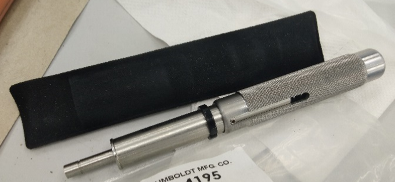
Pocket Penetrometer
The penetrometer is a flat-footed, cylindrical probe that is pushed 6.35 mm deep below the split-core surface.
Objectives
To determine the shear strength in cohesive soils.
Test Procedure
- Choose your test location with care to avoid gravel or other particles that would influence reading. Avoid obviously disturbed areas. For saturated cohesive soils, it is important that readings be taken in “fresh” samples or cut surfaces, since rapid drying will greatly influence the reading.
- Return ring to back position against the penetrometer body, making sure the front edge is at the zero reading, or return the scale indicator to zero (this is dependent on the model you have).
- Grip the handle firmly, insert the shaft 6.35mm in depth with a smooth constant force into the soil mass or sample. The 6.35mm depth is indicated by the line above the tip of the penetrometer.
- Take the reading from the bottom of the indicator ring or scale indicator.
- To convert the readings from kg/cm2 to kPa multiply the result by 98.08.
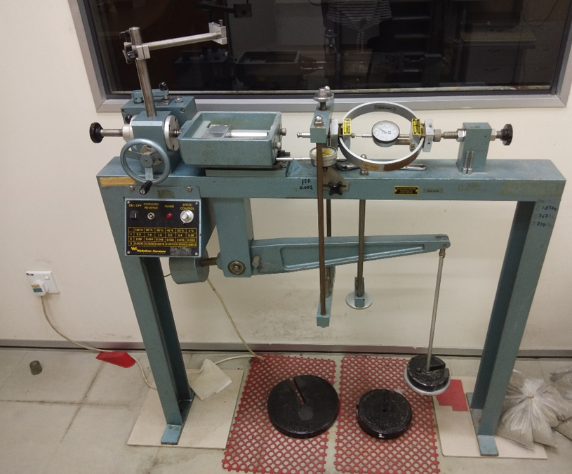
Laboratory Vane Shear
Introduction
The laboratory vane test consists of inserting a four-bladed vane in the end of an undisturbed tube sample or remoulded sample and rotating it at a constant rate to determine the torque required to cause a cylindrical surface to be sheared by the vane. This torque is then converted to a unit shearing resistance of the cylindrical surface area. The torque is measured by a calibrated torque spring or torque transducer that is attached directly to the vane.
Objectives
To determine the shear strength in cohesive soils, is useful for soils of low shear strength of less than about 0.5 kgf/cm2)
Test Procedure
- Fasten the apparatus and the sample securely to a table or frame to prevent movement.
- Insert the vane spring vertically into the right slot.
- Insert the vane blade and drive it into the sample twice the height of the blade.
- Take an initial reading. Ensure that the sample is not moving when the motor is started. (The vane/spring rotation is 60 – 90 degree per min).
- Record spring deflections or torque transducer readings at least every 5 degrees of rotation until the spring deflection does not increase which is considered a failure. Record the maximum torque or final reading.
- Remove the vane blade and clean it.
- Take moisture content test from a representative sample.
- Inspect the soil for inclusions such as sand, gravel, cracking of the failure surface which may influence test results. Record the findings.
- Following the determinations of the maximum torque, the remoulded or residue vane strength can be done by rotating the vane rapidly through a minimum of five to ten rounds. The remoulded or residue strength should be started immediately after completion of rapid rotation and within 1 minute after remoulding process.
- Repeat the whole process from step 1 to step 8.
Unconsolidated Undrained Triaxial
Introduction
This method covers the determination of the undrained strength of a specimen of cohesive soil when it is subjected to a constant confining pressure and to strain-controlled axial loading, when no change in total moisture content is allowed.
The test is carried out in the triaxial apparatus on specimens in the form of right cylinders of height approximately equal to twice the diameter.
In the test the specimen is confined in an impervious membrane between impervious end caps in a triaxial cell which can be pressurized by water. The axial load is increased by applying a constant rate of strain until the specimen fails.
Objectives
To find the shear strength of the soil by Unconsolidated Undrained Triaxial Test.
Apparatus Required
- A drying oven, capable of maintaining a temperature of 105 oC to 110 oC
- A balance readable to 0.01 g
- Triaxial compression machine
- Triaxial cell
- Pressure panel system complete with air/water cylinders
- A dial gauge readable to 0.01 mm – strain
- Proving ring fitted with dial gauge – load
- Brass or plastic ends caps
- Rubber membrane
- Membrane stretcher
- Two rubber O-rings
- Apparatus for determination of moisture content
- Apparatus for specimen preparation and measurement
- Cling wrap
- Mechanical extruder
Test Procedure
1. Preparation of specimen
- The specimen shall have a height equal to about twice the diameter.
- Remove the soil from its sample tube using mechanical extruder.
- Measure the length Lo (in mm), diameter Do (in mm) and mass m (in g) of the specimen accuracy to enable the bulk density to be calculated to an accuracy of ±1 %.
- Seal the specimens that are not to be tested to prevent loss of moisture.
- After preparing the test specimen, break open the remainder of the sample and record a detailed description of the soil and determine the moisture content, wo (in %).
2. Setting up
Mount the test specimen prepared as follows.
- Place the base end cap centrally on the base pedestal of the triaxial cell, ensuring that it is in correct vertical alignment.
- Place the specimen on the base end cap and place the top cap on the specimen.
- Fit the rubber membrane evenly on the stretcher.
- Place the membrane around the specimen while applying suction to the stretcher.
- Seal the membrane to the end caps by means of rubber O-rings.
- Assemble the cell body with the loading piston well clear of the specimen top cap. Check alignment by allowing the piston to slide down slowly until it makes contact with the bearing surface on the top cap, then retract the piston.
- Fill the triaxial cell with water, ensuring that all the air is displace through the air vent.
3. Pressurising the cell
Pressurise the triaxial cell and make final adjustments as below.
- Raise the water pressure in the cell to the desired value with the loading piston restrained by proving ring.
- Adjust the loading machine to bring the loading piston to within a few millimeters of its seating on the specimen top cap.
- Adjust the machine further to bring the loading piston just into contact with the seating on the top cap.
- Select a rate of strain. Engage the appropriate gear on the triaxial compression machine.
4.Compression test
- Start the test by switching on the machine.
- Record readings of the proving ring (load) and dial gauge (strain) at regular intervals of the latter.
- Continue the test until the maximum value of the axial stress has been passed and the peak is clearly defined, or until an axial strain of 20 % has been reached.
5.Unloading and removal
- Stop the test and remove the axial force.
- Drain the water from the cell, dismantle the cell and remove the specimen.
- Remove the rubber membrane from the specimen and record the mode of failure with the aid of a sketch.
- Break open the specimen and record a description of the soil.
Direct Shear Box
Introduction
The Direct Shear Test is an experimental procedure conducted in geotechnical engineering practice and research that aims to determine the shear strength of soil materials. Shear strength of soil is its maximum resistance to shearing stresses.
Generally, the Direct Shear Test is considered one of the most common and simple tests to derive the strength of a soil and can be performed on undisturbed or remoulded samples.
Objectives
To obtain ultimate shear resistance, angle of internal friction and shear stress deformation characteristics of cohesionless soils.
Apparatus Required
- Shear box
- Shear box container
- Base plate with cross groves on its top
- Porous stone (2 nos)
- Plain grid plates (2 nos)
- Perforated grid plates (2 nos)
- Loading pad with steel ball
- Digital weighing machine
- Loading frame with loading yoke
- Providing ring
- Dial gauges
- Weights
- Spatula
- Sampler
Test Procedure
- Placing a soil specimen in the inner dimensions of sampler 60mm x 60mm in plan which are also inner dimensions of shear box. The thickness of box is about 50mm while the thickness of sample should be 25mm.
- Now attach the two halves of the shear box with locking pins and place the base plate at the bottom.
- Above the bottom plate, Place the porous stone and above it place the grid plate. Plain grid plates are used for undrained conditions while perforated grid plates are used for drained conditions.
- Now we have baseplate, porous stone and grid plate in the shear box. Weigh the box at this stage and note down.
- After that place the soil specimen above the grid plate. Undisturbed sample is directly transferred to shear box. If sandy soil is using, place it layers wise and tamper the each layer to get the required density.
- Note down the weight of shear box with soil specimen.
- Above the soil specimen, place the upper grid plate, porous stone and loading pad one above the other.
- Now the whole box is placed in a container and mounted on the loading frame.
- Proving ring is arranged in such a way that it should contact the upper half of the shear box.
- Loading yoke is placed on the steel ball of loading pad of shear box
- Two dial gauges are fitted one to the container for measuring shear displacement and other one is to the loading yoke for measuring vertical displacement.
- Now locking pins are removed from the shear box and spacing screws are placed in their respective positions of the box.
- The upper half of the box is raised slightly with the help of spacing screws. The spacing is decided depending upon the maximum size of particle.
- Now apply the normal stress which is generally 25 kN/m2. Also apply the shear load at a constant rate of strain.
- Now the box starts reacting to loads applied and for every 30 seconds note down the readings of proving ring and dial gauges.
- If the proving ring reaches maximum and suddenly drops it, means the specimen is failed. Note down the maximum value which is nothing but failure stress.
- For some soils, failure point is taken at 20% of shear strain.
- Finally remove the box and measure the water content of the specimen.
- Repeat the same procedure for different normal stresses of 50, 100, 150,200,250,300,400 kN/m2
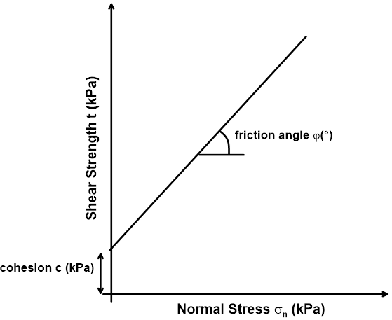
In soil mechanics, the shear strength is evaluated using the Mohr-Coulomb (M-C) Failure Criterion. The M-C Criterion assumes that the shear strength depends on three factors:
- The normal effective stress (σn)
- The friction angle of the material (φ)
- The cohesion of the material (c)
The qualitative correlation of those components is expressed as:
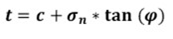
Now plot a graph between normal stress and shear stress by taking normal stress on abscissa and shear stress at failure on ordinate. The graph looks like as shown below.
Point Load Index
This is a placeholder tab content. It is important to have the necessary information in the block, but at this stage, it is just a placeholder to help you visualise how the content is displayed. Feel free to edit this with your actual content.
Consolidation Test
Introduction
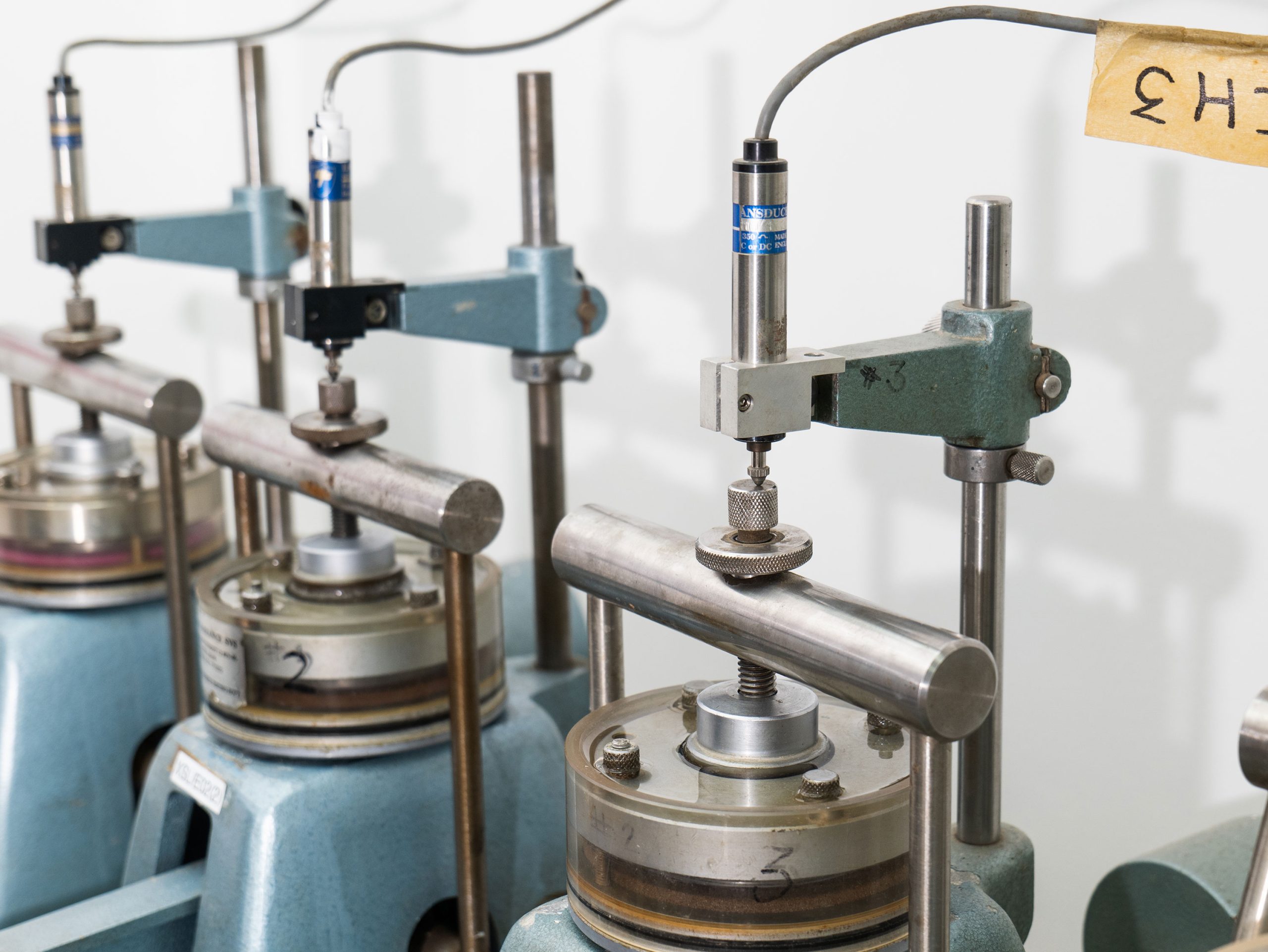
The simplest case of consolidation examined is the one-dimensional consolidation. In this case, the lateral strain of the soil mass is neglected. The testing procedure to quantify the critical soil properties associated with soil consolidation is the Oedometer Test. The term “Oedometer” derives from the Ancient Greek language and means “to swell”. The test is one of the most commonly conducted, and important, laboratory tests in geotechnical engineering. The Oedometer Test aims at measuring the vertical displacement of a cylindrical, saturated soil sample subjected to a vertical load while it is radially constrained. In the subsequent test, the incremental loading consolidation test is described. Note that there is also a constant rate of strain (CRS) test that nowadays is becoming more popular.
Objectives
To determine the rate and magnitude of soil consolidation when the soil is restrained laterally and loaded axially.
Apparatus Required
A typical Oedometer test set-up is composed of: i) a consolidation cell, ii) a loading frame, and iii) a deformation measurement mechanism.
The consolidation cell consists of the following components:
- Confining ring, placed circumferentially around the sample to restrict the lateral displacement
- Loading cap, to transfer the load to the soil specimen
- Reservoir, filled with water to ensure that the soil remains essentially saturated
- Porous stones, which are several orders of magnitude more permeable than typical samples of fine-grained soil. These stones enable the drainage of the water from the top and bottom of the specimen
- Filter papers, placed between stone and soil sample to prevent soil from clogging the pores of the stone
The loading frame configuration is composed of a loading beam and dead weights. The configuration allows for a constant load to be maintained indefinitely. The application of the load causes deformation of the loading frame, the porous stones and the soil sample. Since the test is intended to measure only the deformation of the soil, the other movements (machine deflections) must be measured and later subtracted from the total deformation. This is achieved by measuring the deflection of the set up using an aluminum sample, which is characterized by linear elastic, and thus known, response.
The vertical deformation measurements of the soil specimen is performed using a dial gauge (most often) or an electronic instrument.
Test Procedure
- Position the dial gauge (or electronic instrument)
- Measure weight, height, diameter of the confining ring
- Measure height (H) and diameter (D) of aluminium sample
- Trim specimen into the confining ring
- Take water content measurement from the trimmings
- Weigh soil sample and confining ring
- Soak porous stones and filter papers
- Place the consolidation cell in the loading frame and adjust height. The loading beam should be almost horizontal.
- Take initial reading (Ri – reading will be subtracted from all measurements)
- Place seating load
- Add water to the reservoir
The load is maintained for a period of 24 hours (in certain clays the required time is 48 hours) during which the soil consolidates with drainage from the porous stones. Afterwards, the applied load is increased incrementally by doubling the applied stress at each stage. The number of the load stages and the maximum stress applied depends on the stress range of interest. During the loading process, water is provided into the cell so that the specimen remains fully saturated. At each loading stage, readings of deformation are taken systematically to develop a time-settlement curve. That is, after the application of each load, the deformation is measured at 6, 15, 30 seconds, then at 1, 2, 4, 8, 16, 30 min and at 1, 2, 4, 8 and 24 hours, respectively. When the maximum load is reached, and possibly in a load increment in between, an unloading stage is introduced that may be conducted in one or multiple steps; typically, the load is reduced by a factor of 4 at each step. When the test is completed, the final height of the sample and its water content are measured.